PRECISION PRODUCTS:
 IMS has developed precision products for over ten years, although many have been developed for others under strict Non Disclosure Agreements (NDA), so it goes without saying that several of our products are used in manufacturing, aerospace, medical, automotive, energy, weapons, and research institutions worldwide, although one may never know it. IMS is proud to work with people to solve complex technical problems, in fact, that’s our passion, i.e., providing engineering solutions that make a difference, thus putting aside notoriety. Nonetheless, we have developed some products for market and proud to share them with you.
Below are examples of precision products from IMS:
QUICK-REPEAT COUPLING
 IMS has developed a highly repeatable work-holding fixture to enable fast, in-process inspection between an ultra-precision turning and/or grinding machine and a metrology instrument such as a coordinate measuring machine (CMM). Designed to quickly engage and disengage, the coupling is estimated to repeat its position to <1 μm while supporting up to a 10 kg payload. The coupling features micro-finished tungsten-carbide spheres and quarter cylinders configured as a three-vee kinematic coupling. The nesting force (or preload) is applied with a quarter-turn latch mechanism acting through a spring plate and cross-axis cam followers to eliminate sliding friction. The coupling also features a labyrinth seal to exclude coolant and debris from contaminating the contacting surfaces.
Purpose: The Quick-Repeat Coupling (QRC) enables the workpiece and its supporting fixture to be moved from the manufacturing machine to the inspection machine and returned for subsequent work without further adjustment or compensation of position or orientation. To be useful, the QRC must be repeatable, robust and rapidly engaged and disengaged.
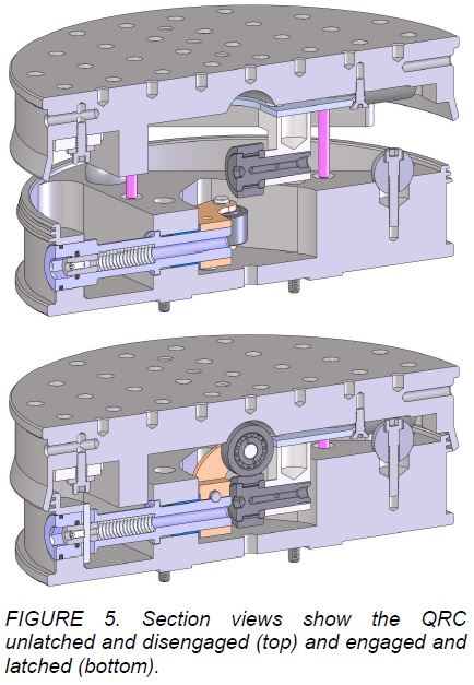
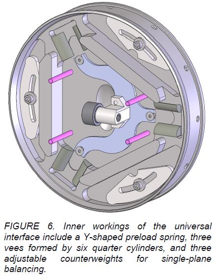
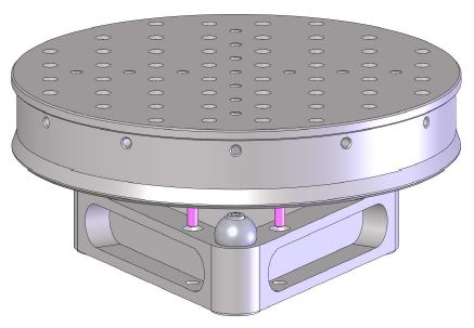
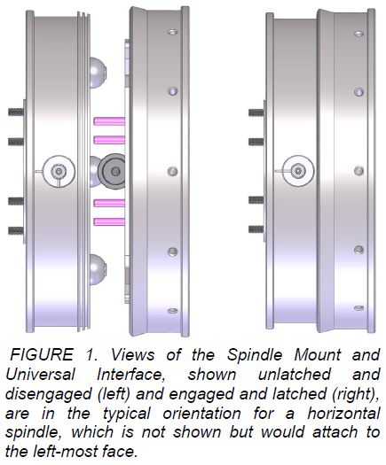
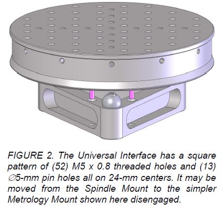
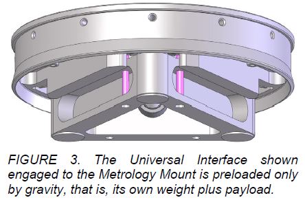
Description: The Quick-Repeat Coupling typically includes three separate assemblies: the Spindle Mount, the Metrology Mount and the Universal Interface which holds the workpiece and will couple to the two mounts as shown below in FIGURES 1, 2 and 3. The contacting surfaces, visible in FIGURES 4 and 6, are configured as a three-vee kinematic coupling. For the Spindle Mount, which typically has a horizontal axis, the surfaces are held in contact by a compliant mechanical latch that the operator turns using a T-handle hex key (8 mm or 5/16 in). The simpler Metrology Mount is gravity loaded and can only be used with a vertical axis. In addition, the QRC has the following notable features:
- The QRC is 8 inches [203 mm] in diameter and 2.75 inches [70 mm] in overall length. The masses of the Spindle Mount, Metrology Mount and Universal Interface are: 10.1 lb. [4.6 kg], 2.2 lb. [1 kg] and 13.4 lb. [6.1 kg], respectively.
- The Spindle Mount attaches to the face of a Precitech SP150LC spindle using the same bolts as the standard vacuum chuck.
- The coupling is designed to operate at a maximum spindle speed of 5000 rpm.
- The mechanical latch works as a toggle mechanism with cross-axis cam followers and a spring plate to provide a repeatable nesting force up to 200 lb. [890 N] with minimal friction to influence positioning, see FIGURE 5.
- The mechanical latch has a spring-loaded catch to secure the latched position, which is visibly indicated with alignment marks. To disengage the coupling, the operator must release the catch by pushing in with the T-handle and then rotating ± 90° to one of the unlatched positions.
- The coupling geometry and materials were chosen for a combination of repeatability, stiffness and robustness. The contacting surfaces are micro-finished tungsten-carbide spheres and quarter cylinders, all with 3/4″ inch [19 mm] diameter. The repeatability is estimated to be <1 μm while supporting a 10 kg payload. The stiffness is estimated to be >200,000 lb/in [35 N/μm]. Repeatability, stiffness and load capacity are taken at a point representing the center of the workpiece, 1 inch [25 mm] from the face of the Universal Interface.
- The six contact surfaces critical for repeatability are protected from grinding debris and coolant using a non contacting labyrinth seal, see FIGURE 5. In addition, these surfaces are accessible for occasional cleaning.
- Reference surfaces are provided on both the Spindle Mount and the Universal Interface to: enable concentric setup to the spindle, serve as datums for the CMM and verify repeatability.
- Four asymmetrical guide pins prevent accidentally engaging the coupling in the wrong angular orientation. They also serve as legs if the Universal Interface is placed on a table.
- The Spindle Mount has two adjustable counterweights for balancing as an independent assembly. The Universal Interface has three adjustable counterweights and is balanced while engaged with the Spindle Mount. The workpiece and its supporting fixture are balanced using radial set screws in the Universal Interface (see FIGURES 4 and 6).
- The exterior housings are constructed of hardened stainless steel.
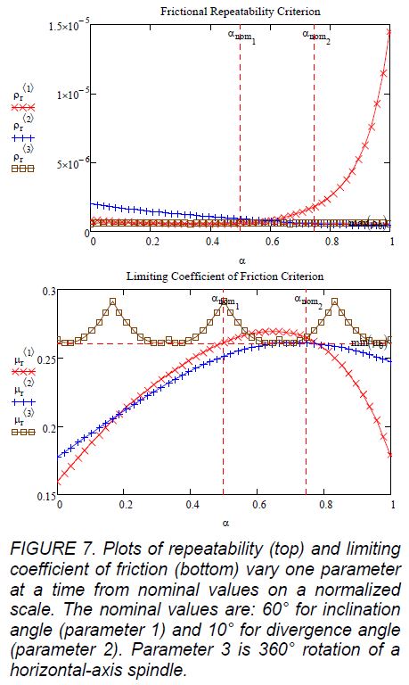
Design Analysis: The requirement that the QRC must work on a horizontal-axis spindle makes the design process more challenging for several reasons but in particular, the performance will suffer compared to a more favorable orientation. A horizontal-axis coupling must be preloaded with a higher nesting force to hold all the kinematic surfaces in contact. As a rule of thumb, the ratio of the highest to lowest contact force should be of order 2:1 or less. Higher force leads to proportionally higher friction and greater positioning error because stiffness is increasing only to the one-third power.
The analytical model developed for the QRC estimates the positioning error (or repeatability) based on the real coefficient of friction (assumed to be 0.1) and the stiffness of the contacting surfaces. Using the payload and nesting force stated earlier, the model predicts little change in repeatability between a horizontal axis at 0.875 μm and a vertical axis at 0.818 μm. The significant improvement comes by reducing the nesting force. For example, the repeatability for the gravity-loaded Metrology Mount is predicted to be 0.231 μm.
It is possible that a kinematic coupling can become stuck well out of position when the restoring force is too small to overcome friction in the contacting surfaces. This is especially true of a coupling with a horizontal axis and is the basis for the rule of thumb stated earlier. An analytical measure of this condition is the limiting coefficient of friction, where the coupling is on the verge of sliding or not. Having a limiting coefficient of friction much larger than the real (or material) coefficient of friction is desirable and can be thought of as a factor of safety.
The analytical model also calculates the limiting coefficient of friction. The QRC oriented with a vertical axis has a 0.36 limiting coefficient of friction independent of the nesting force. Using the payload and nesting force stated earlier (200 lb.), the QRC oriented with a horizontal axis has a 0.25 limiting coefficient of friction. Reducing the nesting force by 2x reduces it to 0.15, which very likely could stick. Increasing the nesting force by an unpractical 10x increases it to 0.35, nearly the value for a vertical axis.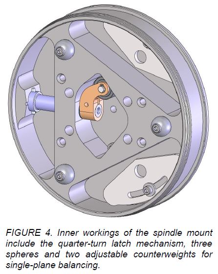
These two measures, repeatability and limiting coefficient of friction, may be used to optimize the configuration of the contacting surfaces, the magnitude and/or direction of the nesting force, and other design parameters. The basic configuration of the QRC was selected to be a symmetric three-vee coupling and the size was fairly constrained. Two angle parameters remain to describe the shape of the vee. The obvious one is the inclination angle (the complement of one-half the included angle of the vee). The other angle can be represented a couple of ways but there is a manufacturing preference. The quarter cylinders that form the vee need not have parallel axes; that is, they could have a divergence angle measured from the radial axis of symmetry.